Introduction
The SIEMENS S7 PLCs are not time deterministic systems, which means the PLC cycle time fluctuates based on how much work it processes. This is a significant difference from many time deterministic systems like Rockwell (Allen-Bradly) and B&R with which you can specify each PLC tasks’ cycle time and schedule them.
Though it is not always the case, time deterministic systems don’t normally support interrupts or they tend to limit their usage while none time deterministic systems like the SIEMENS S7 systems support interrupts well.
In this article, I’m going to demonstrate how to use the hardware interrupt with a S7-1511C PLC, PLCSim Advanced and the PLCSim Advanced API. The use case is to measure the duty cycle of a pulse width modulation (PWM) signal.
If you are interested in learning more about the different organization blocks in a S7 PLC system, you can check out this article.
If you want to learn more about the PLCSim Advanced API, you can check out this article.
Let’s go.
PWM Signal and Its Duty Cycle
Below is an example of PWM signals with different duty cycles. In the below picture, the time for the signals to jump from 0 to +V is the same but the time the signal drops are different. Hence we say that the PWM signals have the same period but different duty cycle.
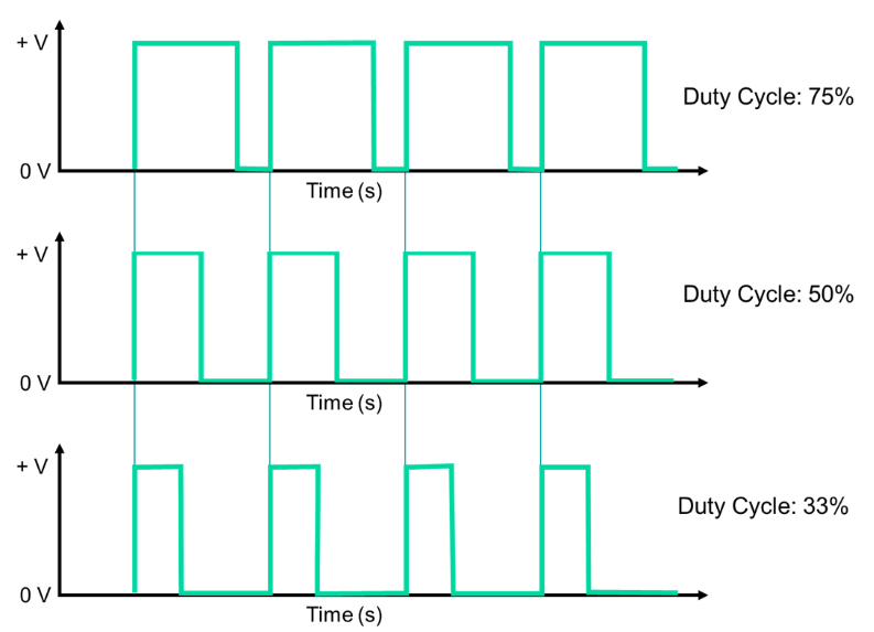
Though the PLCs are well equipped to generate different PWM signals (mainly for driving pulse controlled servo controllers), there isn’t an obvious way to measure the inputting PWM signals’ duty cycle. And this is exactly what this article is addressing.
Hardware Interrupt Configuration
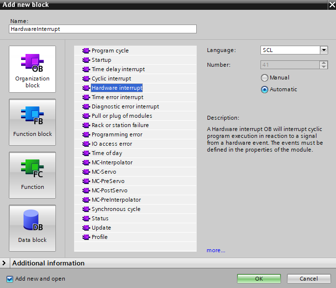
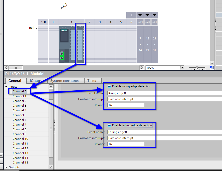
Since the interrupt is driven by the hardware, we need to start with the hardware configuration. In this demonstration, I’m using a S7-1511C PLC because it has integrated digital inputs that support hardware interrupts (Not all IO modules support this feature, only the high feature modules do).
Simply specify the digital input channel that will receive the PWM input signal and attach the hardware interrupt OB to it.
Hardware Interrupt Program
The program to measure the PWM signal duty cycle is written in the hardware interrupt OB. The association between the hardware interrupt and the hardware interrupt OB is done in the hardware configuration (it is also possible to do it with a user program using attach and detach command).
The interrupt program is simple. It relies on the event type to differentiate the rising edge event and the falling edge event and log the time of the input signal change. The time difference between two rising edge events is the input signal’s period and the time between the first rising edge event and the falling edge event is the input signal’s on time. The duty cycle is an easy calculation from this point onwards.
The program that I wrote is quite simple and has a few points to improve.
- Instead of using a TON, the program can use system tick to save resources.
- The interrupt program can be used to only log the edge event time and leave the calculation in another block in cyclic OB.
FUNCTION_BLOCK "pwmMeasure"
{ S7_Optimized_Access := 'TRUE' }
VERSION : 0.1
   VAR_INPUT
      In_EventType : Byte;
   END_VAR

   VAR_OUTPUT
      Out_DutyCycle : Real;
   END_VAR

   VAR
      DutyCycleTimer {InstructionName := 'TON_TIME'; LibVersion := '1.0'; S7_SetPoint := 'False'} : TON_TIME;
      Steps { S7_SetPoint := 'True'} : Byte := 10;
      DutyCycleMeasurement : Struct
         FirstRisingEdge : DInt;
         FallingEdge : DInt;
         SecondRisingEdge : DInt;
         DutyCycle : Real;
      END_STRUCT;
   END_VAR

   VAR CONSTANT
      "Step1: Start Duty Cycle Measure" : Byte := 10;
      "Step2: Catch Falling Edge" : Byte := 20;
      "Step3: End Duty Cycle Measure" : Byte := 30;
      "Step4: Calculate Duty Cycle" : Byte := 40;
      RisingEdge : Byte := 16#1;
      FallingEdge : Byte := 16#2;
   END_VAR


BEGIN
	#DutyCycleTimer(IN := TRUE,
	                PT := T#10s);

	CASE #Steps OF

	    #"Step1: Start Duty Cycle Measure":

	        IF #In_EventType = #RisingEdge THEN
	            #DutyCycleMeasurement.FirstRisingEdge := TIME_TO_DINT(#DutyCycleTimer.ET);
	            #Steps := #"Step2: Catch Falling Edge";
	        END_IF;

	    #"Step2: Catch Falling Edge":

	        IF #In_EventType = #FallingEdge THEN
	            #DutyCycleMeasurement.FallingEdge := TIME_TO_DINT(#DutyCycleTimer.ET);
	            #Steps := #"Step3: End Duty Cycle Measure";
	        END_IF;

	    #"Step3: End Duty Cycle Measure":

	        IF #In_EventType = #RisingEdge THEN
	            #DutyCycleMeasurement.SecondRisingEdge := TIME_TO_DINT(#DutyCycleTimer.ET);
	            #Steps := #"Step4: Calculate Duty Cycle";
	        END_IF;

	    #"Step4: Calculate Duty Cycle":

	        #DutyCycleMeasurement.DutyCycle := 1 - DINT_TO_REAL(#DutyCycleMeasurement.FallingEdge - #DutyCycleMeasurement.FirstRisingEdge) / DINT_TO_REAL(#DutyCycleMeasurement.SecondRisingEdge - #DutyCycleMeasurement.FirstRisingEdge);
	        #Steps := #"Step1: Start Duty Cycle Measure";
	        RESET_TIMER(#DutyCycleTimer);

	END_CASE;

END_FUNCTION_BLOCK
PLCSim Advanced API Support and Demonstration
With PLCSim Advanced API, I can simulate the PWM input signal without any hardware support and it is extremely easy. Simply the below lines of code do the job.
            while (true)
            {

                if (!pwmTimer.IsRunning)
                {
                    pwmTimer.Start();
                }

                else if (pwmTimer.IsRunning && !risingedgeTriggerd && pwmTimer.ElapsedMilliseconds >= 600 && pwmTimer.ElapsedMilliseconds <1000)
                {
                    module.instance.ProcessEvent(258, 0, EProcessEventType.RisingEdge, out seqNum);
                    //Console.WriteLine(pwmTimer.ElapsedMilliseconds);
                    risingedgeTriggerd = true;
                }

                else if (pwmTimer.IsRunning && pwmTimer.ElapsedMilliseconds >= 1000)
                {
                    //Console.WriteLine(pwmTimer.ElapsedMilliseconds);
                    pwmTimer.Restart();
                    module.instance.ProcessEvent(258, 0, EProcessEventType.FallingEdge, out seqNum);
                    risingedgeTriggerd = false;
                }


            }
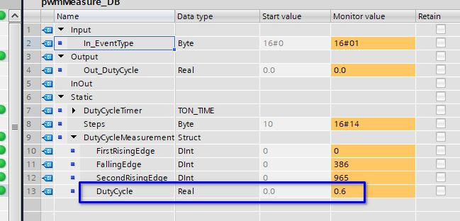
When running the PLCSim Advanced instance and the API program at the same time, the simulated 1Hz PWM signal has 60% duty cycle and as shown on the PLC side, the calculated duty cycle is fairly close to 60%.
Conclusion
The hardware interrupt can break certain important signals free from the limitations of the PLC cycle time and allow us to respond to the signals on priority with minimum resources. This article demonstrated the use case of utilizing the hardware interrupt to measure an input PWM signal.
In addition, instead of using hardware, this article demonstrates that the hardware behaviour can be simulated by the PLCSim Advanced API.
Additional Information
A natural question to ask is how to do the similar thing with a time deterministic system like Rockwell and B&R. I have the experience to do the same with a B&R system. The approach is to use an IO Module with the time stamp feature (similar to the use of the HF modules in SIEMENS). With this kind of module, the signal changes are logged with time stamps and the PLC can use the time stamps to calculate the period and duty cycle.