Introduction
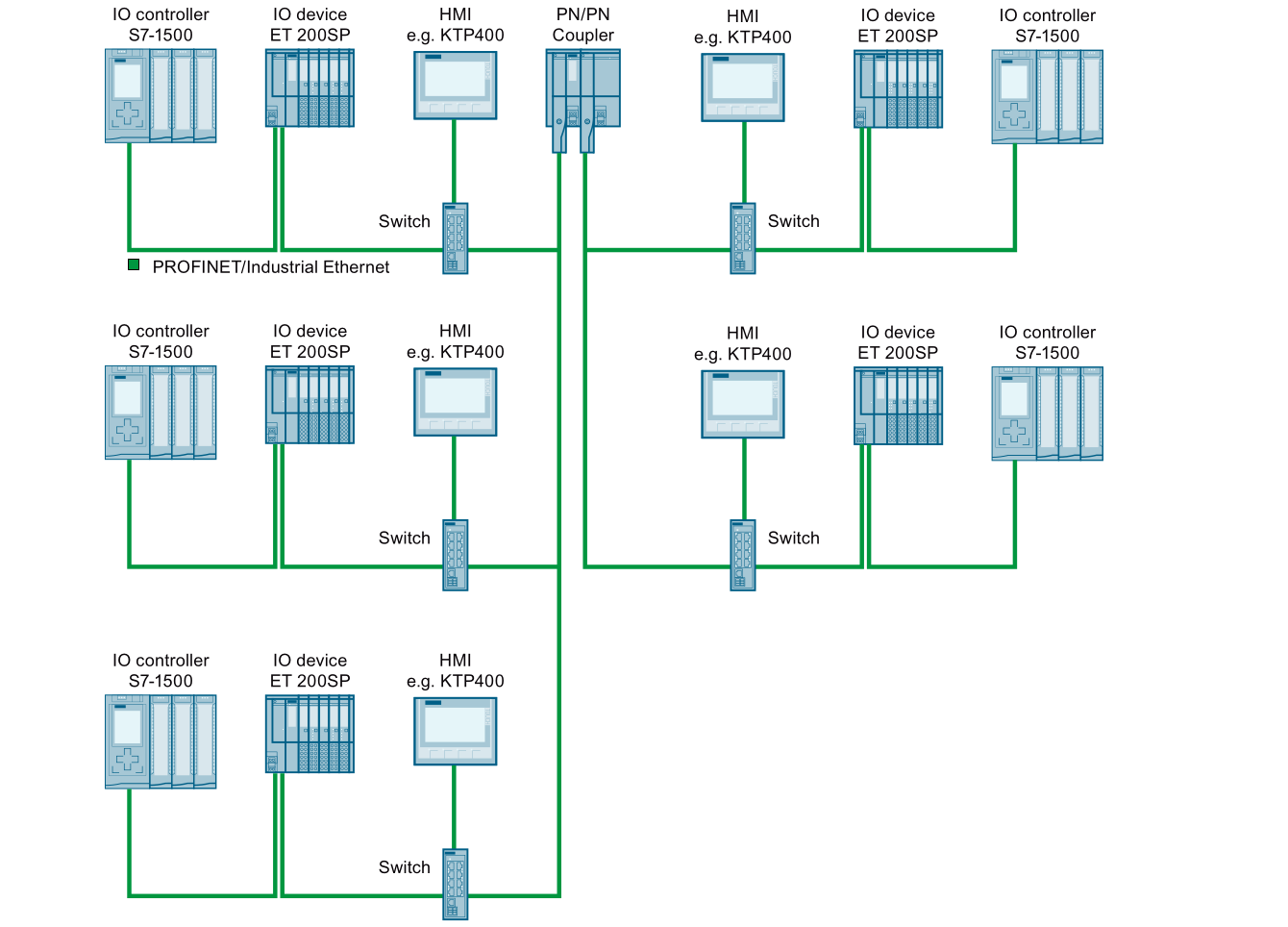
The SIEMENS PN/PN coupler is a gateway device that can connect two separated PROFINET subnets together. It allows the two subnets to exchange certain data but prevents the two subnets’ devices from accessing the other side.
While most of the engineers know how to use the synchronous PROFINET IO communication when each side of the PN/PN coupler is an IO device of an IO controller (normally a PLC), there are many advanced applications that the PN/PN coupler supports.
In this article, I am going to introduce a few advanced PN/PN coupler applications including module-internal shared input / output (MSI, MSO, local MSI, local MSO) and the acyclic data communication (STO / PUB).
Shared Device
PN/PN Coupler Shared Device
PN/PN coupler supports the PROFINET shared device function, which means each side of the PN/PN coupler can be an IO device of more than one IO controller.
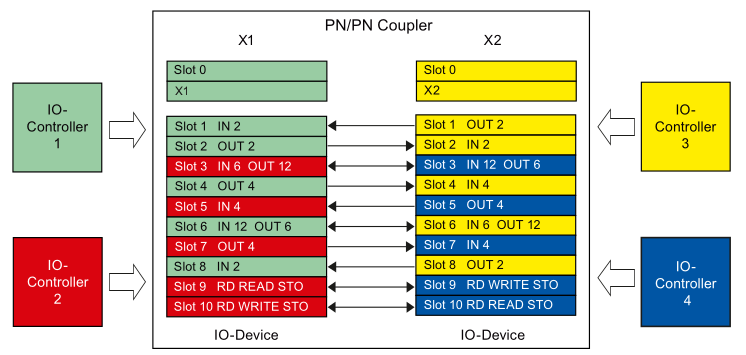
Below is the concept of the PN/PN coupler’s shared device data exchange. On each side of the PN/PN coupler there are two IO controllers, they use different slots of the PN/PN coupler to exchange data and won’t affect each other.
It is important to note that not only cyclic data communication can be shared, the acyclic data exchange can also be shared between IO controllers as shown in slot 9 and 10.
Each side of the PN/PN coupler can be shared between two IO controllers.
How to Configure PN/PN Coupler as a Shared Device
A shared device is normally configured in two different PLC projects since it is a way to reduce redundant hardware and simplify the installation.
For more information about the share device, check out this article
Here I have a PN/PN coupler assigned to a PLC as an IO controller in two different PLC projects. PLC1 controls the 1st and 3rd slot, PLC2 controls the 2nd and the 4th slot. Specify the configuration, in PLC1’s project, the PN/PN coupler’s 2nd and 4th slot is specified to be accessed from outside of the project and the same to PLC2’s project.
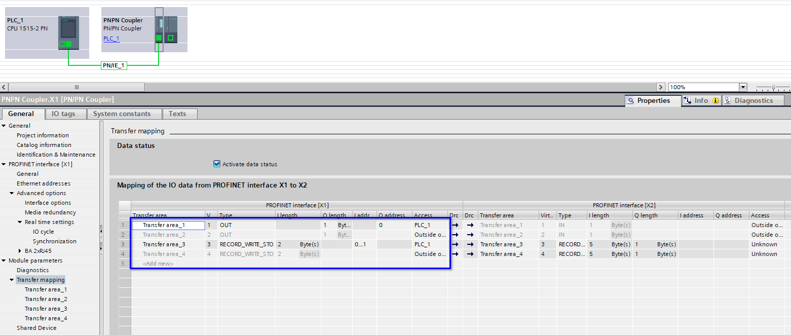
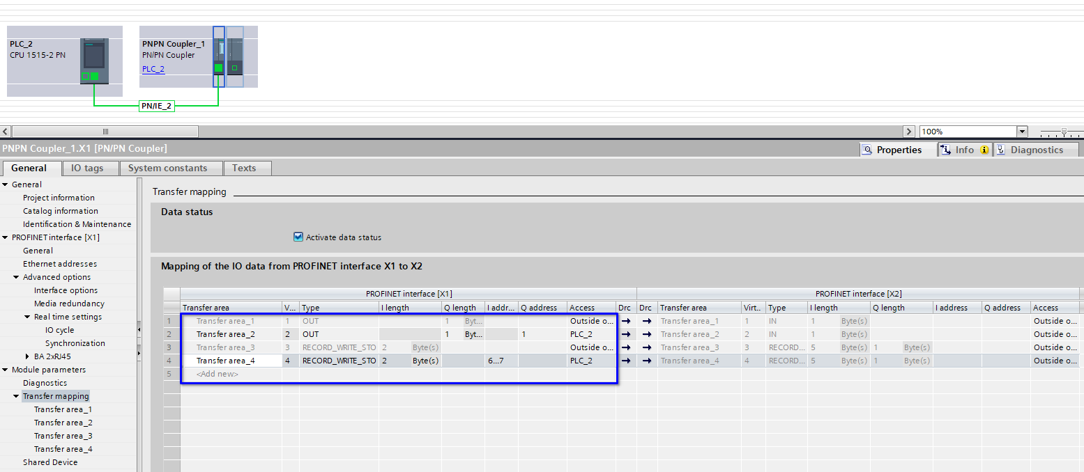
Note that the 1st and 2nd slots are configured as output and the 3rd and 4th slots are configured as STO write. This is to show that a PN/PN coupler can be a shared device for cyclic and acyclic communication.
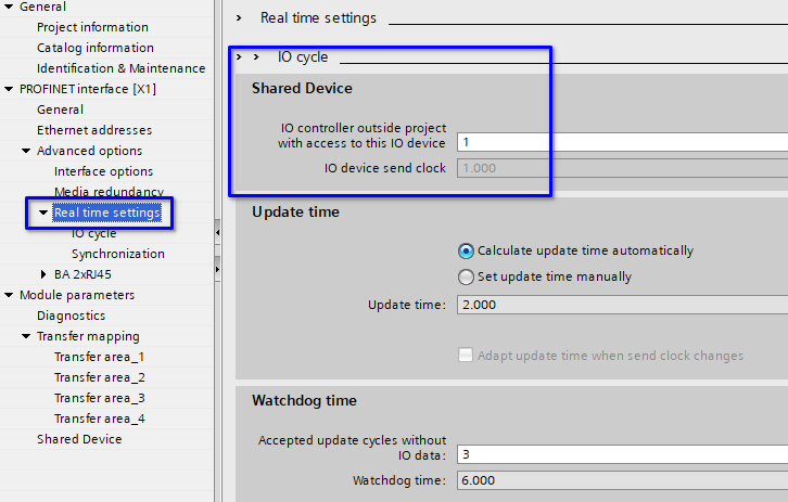
Also in both PLC projects, set the PN/PN coupler’s shared device settings under real time settings as 1 IO controller outside of the project.
The shared device PN/PN coupler configuration is done.
Module Internal Shared Input / Output (MSI / MSO)
Local MSI / MSO
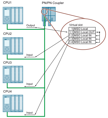
Local MSI / MSO is a special scenario of the shared device feature. Instead of exchanging data between two sides of the PN/PN coupler, we can let one IO controller output the data (Local MSO) and the other up to 3 IO controllers receive the data (local MSI) at the same time.
MSI / MSO
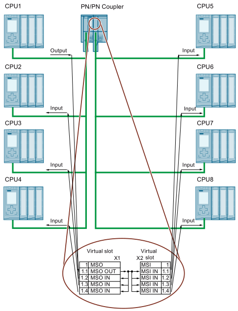
MSI / MSO is similar to the local MSI / MSO and the only difference is that the shared receiving partners are on the other side of the PN/PN coupler.
Below is a scenario of having local MSI / MSO and MSI / MSO at the same time.
How to Configure MSI / MSO
Configuring MSI / MSO / Local MSI / Local MSO is very similar to the shared device hence I won’t provide the details.
Acyclic Data Communication
The widely used cyclic data communication is fine. I can exchange up to 1440 bytes of data with it and it works like a charm.
However, if you have data that doesn’t need to be exchanged in the cyclic manner (fast) and especially when your data is huge, you may not want to let it be exchanged all the time. In these cases, acyclic data communication is your friend (exchange the data only when you need).
Acyclic communication allows you to exchange up to 4096 bytes per PN/PN coupler slot and you can use up to 16 slots of them so up to 65536 bytes at your command. And this communication load only exists when you actually transmit the data so your network load is much better.
PN/PN coupler support two acyclic data communication mechanisms: storage (STO) and publisher (PUB).
Storage (STO) Acyclic Communication
With STO communication, the sender writes the data to the PN/PN coupler’s data FIFO and the FIFO stores up to 8 data. The receiver reads the data from the FIFO from the other side. If the FIFO is full, the sender can write more data to the FIFO until the receiver get at least one data out of the FIFO.
Below is a demonstration of the STO communication mechanism.
Publisher (PUB) Acyclic Communication
With PUB communication, the sender writes one data to the PN/PN coupler and the receiver reads the data from it. PN/PN coupler will not buffer more data. If the sender writes another data to the PN/PN coupler before the receiver reads the previous data, the previous data will be overwritten by the sender.
Below is a demonstration of the PUB communication mechanism.
The above two GIFs are taken from the SIEMENS Limited China technical support department’s public post.
How to Program STO / PUB Communication
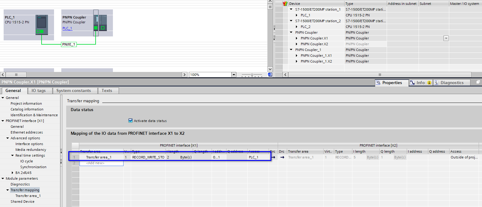
To use the PN/PN coupler transfer data acyclically, the PN/PN coupler’s configuration is simple as shown below.
On the send side, configure a Record_Write_STO or Record_Write_PUB.
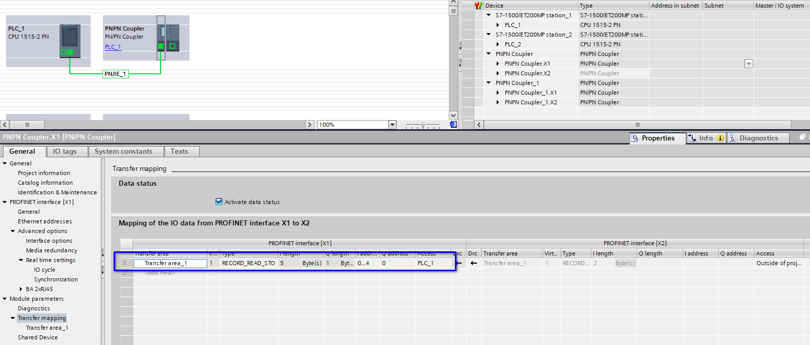
On the receive side, configure a Record_Read_STO or Record_Write_PUB.
Since STO is more useful, I’m using it as an example.
The data transfer relies on the user program to achieve. On the send side, a system FB WR_REC will be used to send the data to the PN/PN coupler and on the receive side, a RD_REC will be used to read the data.
The WR_REC and RD_REC are quite standardized so I won’t discuss it further. However, it is worth noting that on the PN/PN coupler’s data transfer slots there are a few IOs. They are the data transfer status and control IOs. Below are their details and the information about how to use them.
- For STO write.
| IO Address | Used Data | Description | Programming Usage |
|---|---|---|---|
| IB x | Bit 0 | TRUE if PN/PN coupler configuration is ok | Use for diagnosis |
| Bit 1 | TRUE if STO FIFO is not full | Use for diagnosis | |
| Bit 7 | TRUE if data can be written to the PN/PN coupler | Use for diagnosis | |
| IB x + 1 | Whole byte | FIFO usage (0 - 8) | Use for diagnosis |
- For STO read.
| IO Address | Used Data | Description | Programming Usage |
|---|---|---|---|
| IW x | Whole word | Number of data in the FIFO | Use for diagnosis |
| IW x + 2 | Whole word | Data length of next FIFO data to be read | Use for reading the full data |
| IW x + 4 | Whole word | Incrementing number indicating a new data available | Use for acknowledging the data read |
| QB x | Whole byte | Acknowledge the data read | Write IB x + 4 value to QB x to acknowledge the data read |
In short, after a STO read is finished, write the IB x + 4 value to QB x on the data receive side will tell PN/PN coupler that the first data in the FIFO has been read and PN/PN coupler will delete the data and shift the FIFO forward.
- For PUB write.
| IO Address | Used Data | Description | Programming Usage |
|---|---|---|---|
| IB x | Bit 0 | TRUE if PN/PN coupler configuration is ok | Use for diagnosis |
- For PUB read.
| IO Address | Used Data | Description | Programming Usage |
|---|---|---|---|
| IW x | Whole word | Record number read for read | Use for read data record |
| IB x + 2 | Whole byte | FIFO usage (0 - 8) | Use for read data record |
Conclusion
Apart from the most frequently used cyclic communication, PN/PN coupler provides lots of other advanced communication options that can significantly increase the communication flexibility over PROFINET.
In my work, acyclic communication is widely used to transfer product data between PLCs. Since the product data is quite big, the PN/PN coupler’s acyclic communication feature provides a very efficient network bandwidth usage.